
Introduction
An unexpected addition to my homelab, but a welcome one, is the Ender 3 I recently acquired—for free! It’s the perfect opportunity to venture into the 3D printing hobby, offering the freedom to tinker and learn without significant risk. Upon inspection, I identified three minor issues: a missing Z-axis cable, a loose frames, and minor damage to the build plate. The major issue is the print bed being warped. Although, I was unable to achieve my objective, I intend to continue working until I can successfully print the Benchy test print. This will end up being segmented across multiple phases, this is part 1 of a my 3D printing initiation journey.
Objective
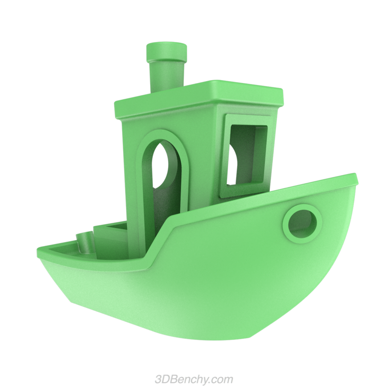
My goal is to test print Benchy with an acceptable level of quality. I hope to achieve this by adhering to the following procedure.
- Evaluate current status of the printer
- Repair when necessary
- Upgrade for better quality prints
Evaluation
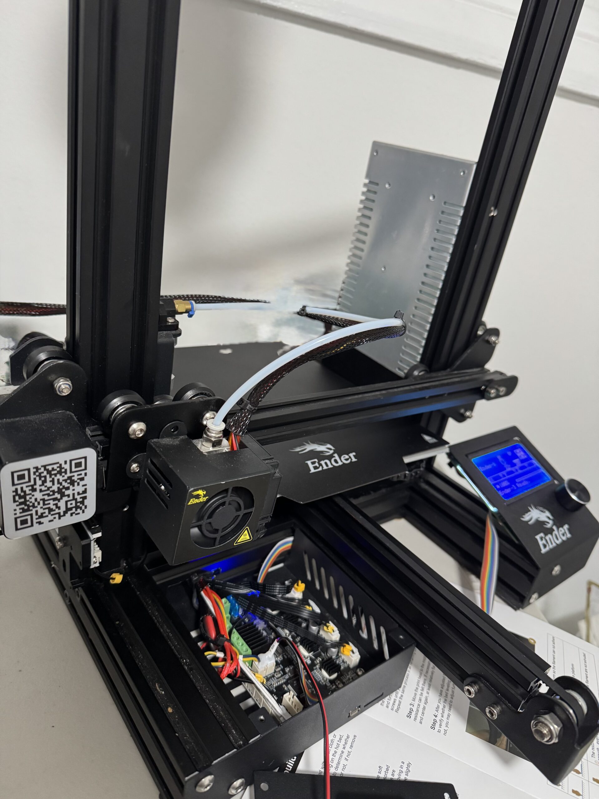
The first step was to simply turn on the printer see how and if it works. Learning along the way the basics of how the printer operates. The printer is a stock Creality Ender 3, which turned on no problem. The load power supply turns on the 8-bit motherboard. Wherein, the board contains
- JST Ports – It seems these ports are used to logically control the printer. As will be explained per function.
- The main axis stepper and extrusion motor control uses four 4-pin ports.
This is how the printer moves in the X, Y and Z direction and the fourth for the extruder motor to feed filament into hotend. - Axis end stops uses three 2-pin ports
This allows the printer to know the limits of the build area and more importantly is how the printer head knows where it is. The printer will auto home itself by moving until the printer head reaches the end stops. - Hotbed and Hotend thermasistors uses two 2-pin ports .
These ports provide heat control for the bed and hotend. - The filament sensor uses a 3 pin port.
I believe the filament sensor is optional and it automatically pauses print when filament is low. - The Z probe such as a CR touch or BL touch uses a 5-pin port .
A Z axis probe is optional. This can be used as a replacement or supplement to the Z axis end stop. The all use cases will be discussed further later but the main idea is to automate bed leveling. - Part and motherboard Fan Control uses two 2-pin port.
The part fan is the smaller fan on the printer head. This fan cools the freshly extruded filament as it leaves the nozzle. - LCD screen with a knob uses a 10-pin port.
This is the main control of the board.
- The main axis stepper and extrusion motor control uses four 4-pin ports.
- Power Ports – It seems these red/black ports apply a constant 24V to each port.
- Input power from PSU.
- Hotend Fan
This fan cools the hotend assembly preventing overheating and ensuring smooth extrusion of filament. - Hot Bed Heater
- Nozzle Heater
- IO Ports – This is used for sending print jobs
- One Micro USB port
- One SD card port
Used for flashing firmware.
Repair
Z Axis Cable … and fan replacement
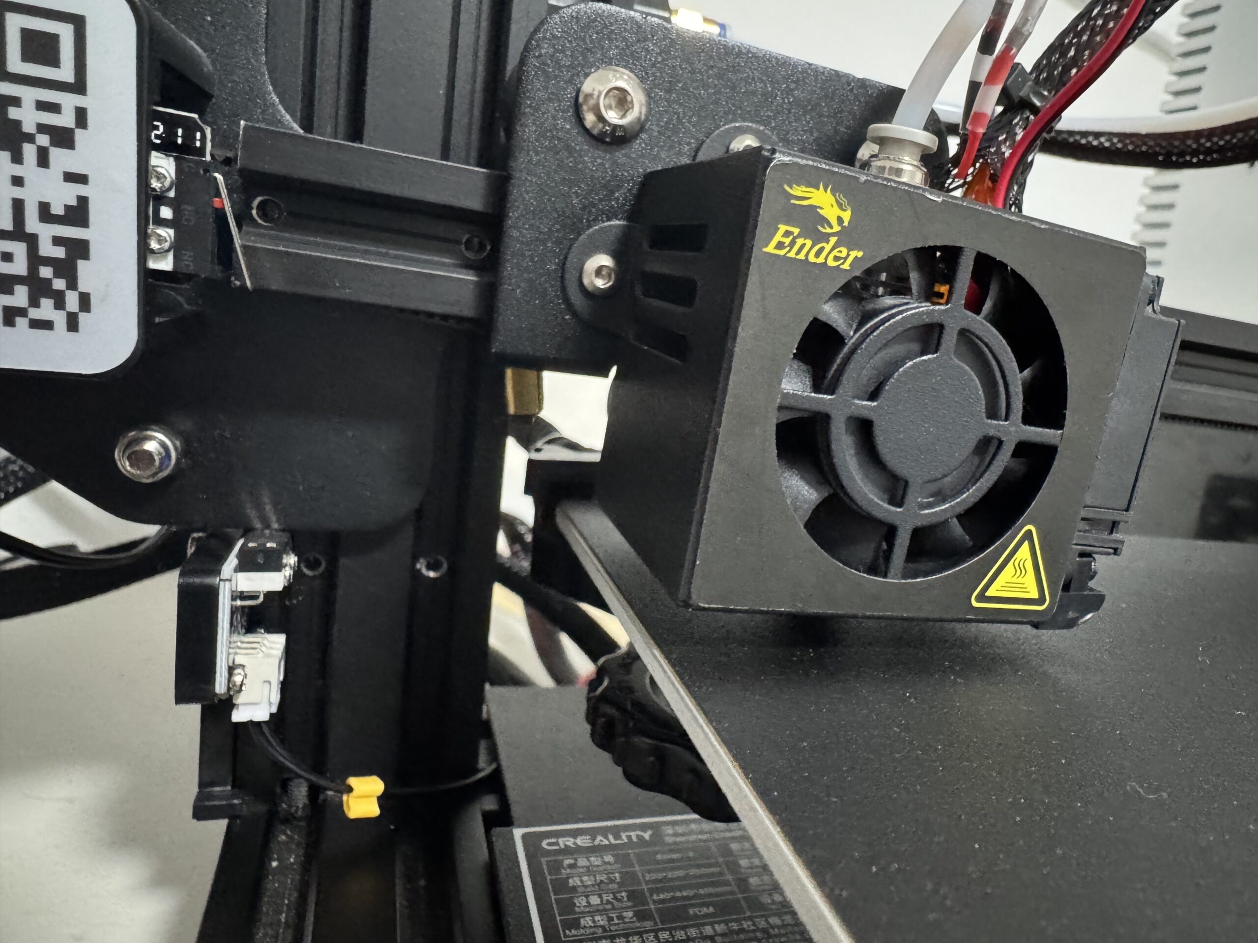
I began by replacing the Z-axis cable. This straightforward fix involved accessing the motherboard, connecting the cable to the negative Z-axis port, and routing it to the home sensor. However, I encountered an unexpected challenge when the metal cover of the motherboard struck the running fan, breaking two blades. While the printer could technically function, I wanted to start right, so I replaced the fan. I spliced the wires using heat-shrink tubing with built-in solder—a simple yet effective solution, though the wires now lack a polished look. I added extra slack to allow for a potential hot-swappable port in the future.
Loose brackets
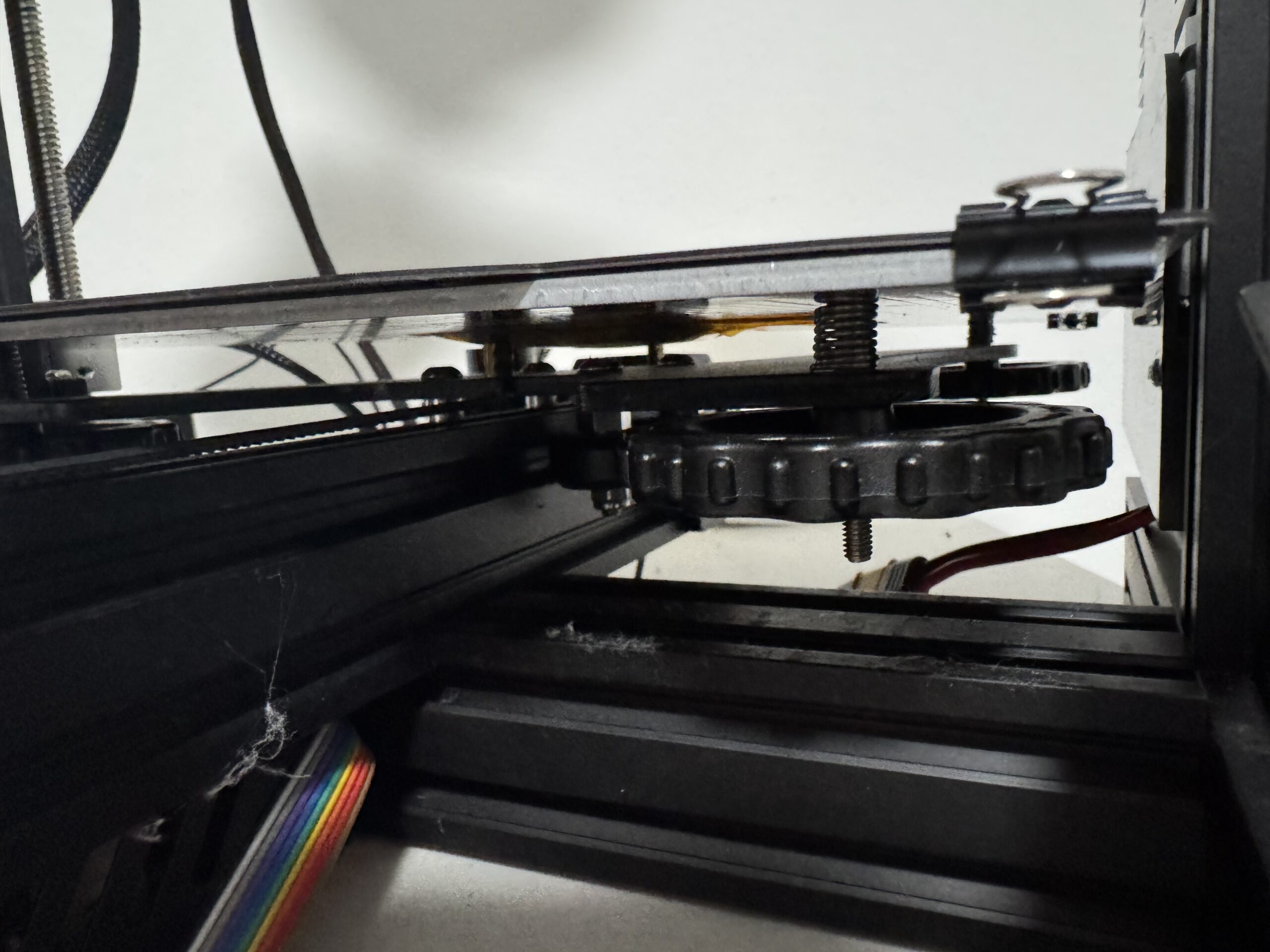
Next, I addressed the wobbly printer head by disassembling it and tightening the three wheels. This didn’t fully resolve the wobbling and, in some cases, made it worse. Further research revealed that tightening the eccentric bolt underneath was the true solution.
Build plate
I have narrowed my build plate design to 3 choises
- Flexible Stock
- A simple sticker design thereby avoiding the binder clips
- Flexible Magnetic
- A 2 part sticker solution. The bottom is a magnetic sticker which applies to the print bed and you place the build surface on top magnetically locking in place.
- Glass
- Presumed to be ideal for users due to its ease of removing prints
- PEI
- Lauded as the best among many enthusiasts
I purchased two replacement plates: a flexible stock one and a magnetic design, with plans to try a PEI and glass plate later. The magnetic plate avoids the need for binder clips, providing more build volume and clearance for the printer head. Meanwhile, the glass plate allows prints to complete without frequent removal of the plate, minimizing the need for re-leveling. Currently, I’m using the stock plate for simplicity.
Bed Leveling
Process
Regarding bed leveling, I followed the standard process of adjusting the screws beneath each corner to achieve the right tension—a snug fit for a piece of paper, allowing slight movement. I also explored an automated process using G-code. This script systematically moves the printer head to key points on the plate for adjustment, followed by a test print for verification. During this test, any fine-tuning can be made as needed. The G-Code had 4 modes:
- Cold No Print
- Cold Print
- Hot No Print
- Hot Print
- Print Only
Warped Bed
This ended up being the main source of my consternation. After running a series of tests, I concluded that the bed is warped. I ran through each test multiple times working my way through each test slowly fine tuning the levels. The print was excellent on each corner but going in between them, the extruder became too close to the bed. On the final run of the print, every time the bed was too high. Therefore, I deduced that my bed had a downward concavity making my current bed leveling technique fairly problematic.
To be continued
Due to time constraints, I am going to segment my efforts into steps. This first step was simple: learning, evaluating and troubleshooting minor issues. I’ve identified a major issue being the warped bed. Although far from complete, this is still considered a success. I have resolved the minor issues and identified the major issue. The next step is to follow through on the Upgrade phase. Primarily, install a new upgraded 32 bit mother board, CR touch and using Raspberry Pi for klipper firmware. Although, I could solve the issue without these upgrades, I figure these upgrades can address the issue while delivering better performance. The further elucidation on the rationale, learning and my implementation will be documented in part 2.
Conclusion
This unexpected addition to my homelab opens up an exciting new avenue for experimentation. While it may momentarily divert my attention from other projects, it’s a worthwhile investment. I already have several 3D printing ideas for both personal and lab-related uses.
Leave a Reply